Level editor
| Level editor topics |
|---|
|
The level editor is used to generate the level layouts that are the basis for creating areas. A level layout is a non-interactive resource; the objects placed within it serve only to provide the physical structure and appearance of the area. If you need the player to interact with objects within an area you'll need to use interactive placeables instead.
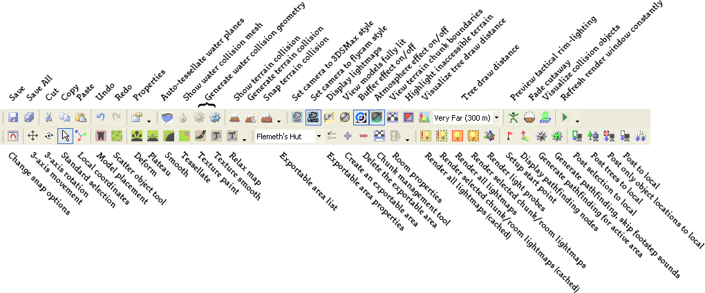
Note that unlike the Area editor, only two modes of camera control are currently supported: "flycam" mode (![]() button in the toolbar) and 3DS Max mode (
button in the toolbar) and 3DS Max mode (![]() button). NWN style is not currently supported. (Use a combination of the mouse wheel + Ctrl or/and Alt (dependant on camera mode) to control the camera. In either mode Numpad 5 will reset the camera.)
button). NWN style is not currently supported. (Use a combination of the mouse wheel + Ctrl or/and Alt (dependant on camera mode) to control the camera. In either mode Numpad 5 will reset the camera.)
Contents
Terminology
- Sector: A sector is a square of geometry and is currently exported to the game as a “Chunk”. For all intents and purposes, we can consider a sector and a chunk to cover the same area. The different term is kept to distinguish between source (sector) and output (chunk). Sectors are always square.
- Chunk: A Chunk is the game-side basic building blocks of Terrain based levels. Each Chunk is self-contained, has its own levels of Detail (LOD), RIMs, model lists, tree lists, etc. It is what is streamed in and out during gameplay.
- Base Resolution: This is the starting resolution of each cell, and can be specified in the wizard.
- Cell: A cell is the basic building block of the terrain geometry. Each cell starts off at the base resolution as a square and is made up of 2 polygons.
- Blend Mask: The blend mask is the mask that is used to paint textures on the terrain. It is a blend16 algorithm, where it blends the highest 4 texture values (out of a possible 16) on each texel to come up with a texture mapped terrain.
- Texture Palette: The texture palette is essentially a list of textures, one after the other. When an artist wants to use a texture to paint on the terrain he/she would add a texture to this palette.
- Blend Texel: These are the building blocks that make up the blend Mask. Each texel is comprised of 4 sets values and each value set is essentially a percentage of how much of that texture on the palette shows up, and a mapping of where it maps onto the mask.
- Tessellation: Tessellation is the breaking up of a cell into more resolution of polygons. For each tessellation level it breaks up each polygon into 4 equal parts.
Interior and exterior levels
There are two basic types of levels; interior and exterior. Many features of these two level types are the same and level editor documentation will generally be applicable to both types unless specifically noted. Their key difference is that exterior levels have a terrain mesh (the "ground") and interior levels don't. Note however that there's no reason why you couldn't use one level type to "fake" the other - for example you could create a an entirely underground cave using an "exterior" level with the terrain mesh as the cave's floor.
Creating a new level
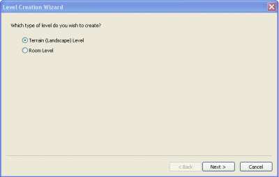
To start the creation of a new level, choose to make a new level through the File menu or by right clicking on the palette. This will present you with a wizard that will set up several basic attributes. Note that some of these attributes can't be changed once the level has been created.
The first choice is whether to have a terrain mesh (the "ground") or not. A Room-based level uses a user-specified visibility graph that connects disjoint rooms together, useful for interiors and dungeon like areas. Rooms are constructed using only existing models created in 3dsmax or another modeling package. In comparison, the Terrain-based level is expansive, with no direct manipulation of what is visible from certain locations. It also contains a terrain mesh that can be manipulated in the editor. Models placement on top of this terrain mesh is similar to the Room-based levels.
If you choose to have a room-based level you'll have to place chunks of floor, walls, and ceiling to enclose the player on all sides. Room-based levels have no further attributes that need to be configured during new level creation, so if you select "room-based" you'll be taken straight to the level editor from here.
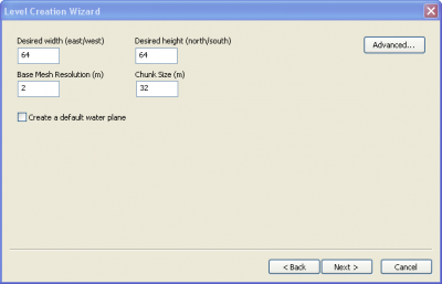
If you choose terrain-based, you'll be asked to define some attributes for the terrain mesh. By default you're shown the basic set of attributes:
- Terrain mesh dimensions, in meters. Note that 64 by 64 is about the minimum that can produce a serviceable level, and that 256 by 256 is the maximum before one starts risking bad performance - though levels can be made larger than this if one takes care.
- Base mesh resolution - determines the size of the individual triangles that make up the terrain mesh. The default has 2 meter triangles. Note however that you'll be able to manipulate the terrain at a much higher resolution than this by using the tessellation tool; each tessellation level splits the previous level's triangles up into four smaller triangles.
- Chunk size - chunks are the basic simulation unit used by the engine. The default 32m is a good chunk size. You'll probably not want to reduce it smaller since you can't have the terrain mesh overhang from one chunk into another; smaller chunks could place limits on the sorts of terrain warping you'll be able to do later.
- Create a default water plane - Creating additional water planes later on is quick and easy, but this option provides a pre-made one by default.
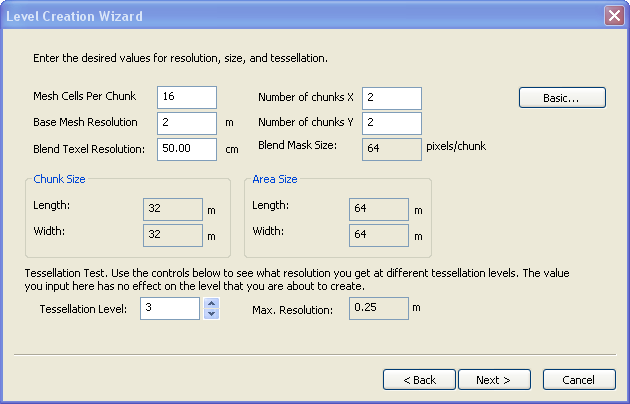
If you click the "advanced" button you'll be provided with a different presentation of the level's dimensions. Instead of defining its dimensions directly you can set how big chunks are and how many chunks there are in each dimension, defining the level's overall dimensions implicitly.
There's one important attribute that can only be set in the advanced pane; the texel map's resolution. A texel is a "texture element", a sort of high-level pixel equivalent that defines a texture instead of just a single uniform colour. The terrain is "painted" with texels, described later.
- Cells Per Sector: This is the number of cells per side of a sector, for example if there are 8 cells per sector, then each sector will have 8x8 cells.
- Base Cell Resolution: This is the length of a single side of a cell in meters. For instance, 8m means that each cell is 8m x 8m.
- Blend Texel Size: This is the length on a single side of a Blend Texel. For instance 100.00cm means that each Blend Texel is 100cm x 100cm (1m x 1m). This is essentially the resolution at which you can paint. It makes sense to set this to something large, which is a good default for the whole level. An artist can set this on a sector by sector basis, later on, in the areas where he/she needs more detail.
- Sector Size: This is the length of a single side of a sector and is reached by multiplying the cells per sector by the base cell resolution (un-editable).
- BlendPageSize: This is the size of the Blend Mask for a Sector/Chunk, and is reached by dividing the sector size by the blend texel size. For instance 64 means the blend mask image for this sector will be 64 x 64. Due to graphics hardware limitations, the actual exported texture may be scaled to a power-2 texture.
- # Cells: This allows the artist to specify the length and width of the terrain level by specifying the number of cells on each side.
- Area Size: This is the length and width of the terrain level in meters, and is reached by multiplying the number of cells by the base cell resolution (un-editable).
- # Sectors: This is the number of sectors/chunks in the terrain world, and is reached by dividing the number of cells by the cells per sector (un-editable).
- Tessellation Level: This is simply to allow the artists to see what resolution they can reach at a given tessellation level, it has no lasting effect on the level. Set this to 4 (max) to see what resolution the artist can reach given the above settings.
- Max. Resolution: This is the maximum poly resolution that the artist can reach given the tessellation level set in the Tessellation field to the left (un-editable).
Toolbar
See sections below for detailed information on level editor specific toolbar buttons.
Terrain mesh
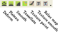
The terrain mesh is a deformable surface used in exterior levels to provide a "ground". This toolbar contains the tools that deals with the terrain mesh:
Each of these buttons brings up a "brush" that's used for various tasks. See Terrain mesh for details.
Other tools
- Chunk boundary visualization - The chunk visualization tool is a button that will highlight where all the chunk/sector boundaries are, allowing the artist to plan the level accordingly. As you can see, it also highlights the models that fall into a colored chunk so that you can see which chunk these will fall into on export.
- Highlight impassible terrain - The game imposes limits on the slope of a walkable surface. Toggling this viewport button will display red highlights on the terrain wherever this limit is exceeded.
- Fade Cutaway Toggle - Cutoff, or 2 meter cutoff as it is called, is where we cut off the tops of models in interiors when we go into tactical camera mode, or overhead camera. This way we can still see the players. The cutoff tool allows the artists to visually see from the editor what will get removed when going into the tactical camera.
- Fade Punchthrough Toggle - Punch through is a system that allows the artists to put a flag on a model to say that it will get “punch through”. What this means is that when the game user is in tactical (overhead) camera mode, any model that is between the main character and the camera will get a punch through mask applied to it. This tool allows the artists to see in the editor what will get punched through in the game.
- Visualize Collision Objects - Turning on the visualize collision toggle will display all collision shapes in green/red wireframes. The green-red tinting is provided to make it easier to distinguish multiple objects from one another.
- Continuous Refresh Toggle - When the continuous refresh toggle is activated, the viewport will constantly redraw whenever it has free CPU time. This is useful for visualizing VFX and another animated models.
Lighting
There are many different types of lighting and light combinations that can be placed in the editor.
There are also many tools used to create lighting and generate lighting and even visualize lighting in the editor. The goal with the editor is to give the artist the same experience as he/she would see in the game. This will help them to be able to create the levels and tweak lighting quickly without having to stop to see it in-game.
Lights for the game are split into two categories based on what they affect: levels and characters. Character lights will affect the player, NPCs, and creatures. The level lights will affect static geometry and designer placeables.
See Lighting for more detail.
Models
Models are used to create any other objects that may be used as part of the level art - walls, floors, ceilings, non-interactive furnishings, visual effects, etc. To place them click on the ![]() icon in the toolbar to go into model placement mode.
icon in the toolbar to go into model placement mode.
Trees are added using the "scatter object" mode (![]() ).
).
See model for more details.
Room visibility and connectivity
Interior based levels have explicit connections between rooms, unlike exteriors where there is an implicit connection between two neighboring chunks. For this reason the connectivity must be set up by the artists. This should be done through planning and iteration as it will affect the streaming and performance of the level in the game.
If you select a room, you will see that that room appears highlighted in red. The Room Properties window can be brought up by pressing the Room Properties button. This behavior can be disabled by unchecking the Highlight visible rooms checkbox. All of the rooms that are visible to this room show up in green. You will see the list of these rooms show up in the Visible Rooms list in the picture above.
The ideal way to generate this visibility information is to press the button called “Generate Visibility Graph”. This will take a little bit of time, so sit back after you press it and be patient. What it does is take a render of each room in the level and generate a list of all rooms that can be seen from it.
NOTE: You must have generated pathfinding data for the level before you generate the visibility info, as it uses the pathing points in this process.
Of course this can be tweaked manually afterwards using the add and remove buttons. However if you ever press the Generate button again it will wipe out all manual changes.
The visibility system is used for streaming as well as the fog of war system, and determining what rooms are visible to the player depending on his/her current room. There is one other factor however to this, the connectivity system, which is detailed next.
The Room Connectivity System is necessary because there are things that can block visibility from one room to another. For instance if I’m looking up a hallway and I can see 3 rooms in the distance, but then I close the door in front of me, the game needs a way to know that those rooms are now invisible. This is where this system comes in.
The room connectivity system can be visualized by the other checkbox under the Connected Rooms list in the Rooms properties window.
Notice that the rooms connected to the current room show up in brown. This is a reminder that you are looking at connectivity and not visibility. As you can see only the rooms that are DIRECTLY connected to the selected room should be in this list. This has to built up manually, by clicking add and then clicking on the rooms that are connected to it. The add button in this case is more of a node, click it, then click the rooms you want to add, then you have to click it again to turn it off. This was done to make adding all the rooms faster.
Trees, grass, and shrubberies
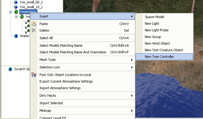
Trees, grass and shrubberies are handled somewhat differently from other models. They are created using a program called SpeedTree that includes information allowing them to respond to the wind. To place trees on a level, you first need to add that tree type's tree controller:
Once this is done you can use the scatter object tool (![]() ) to place specific examples of the vegetation you've added controllers for.
) to place specific examples of the vegetation you've added controllers for.
See Vegetation for a gallery of the vegetation types included with the core resources.
Scatter Object Tool
The scatter object system allows the artist to place down both trees (and grass) and instanced models. An example of an instanced model would be some rocks scattered around on the ground. Objects that are scattered across the terrain level will be placed randomly inside the brush, and will also randomly fluctuate in size and orientation as well.
The Scatter object tool allows the artist to paint scatter object on the terrain. These scatter objects cannot be selected individually, but can only be added or removed with this tool. Left clicking adds scatter objects within the brush, right clicking removes them.
- Fill Rate: This is the rate at which the objects are scattered inside the brush.
- Radius: This is the radius of the brush that adds/removes scatter objects.
When the artist is painting scatter objects, he/she gets a palette, or Scatter Object Selection, from which to select which scatter object to paint. Currently there are 2 tabs, one for trees and the other for instanced models.
The artist can add items to this list by right clicking on the Terrain World and selecting Insert, and then choosing either new Tree Scatter Object or new Model Scatter object. In each case the artist will be able to browse a list of available resources.
- Ignore Density Setting: This allows the artist to ignore the density setting and paint scatter objects in much the same way as one would use a can of spraypaint.
- Maximum Density: This allows the artist to specify the maximum density of scatter objects in the brush radius, and the brush will only paint up to this maximum.
- Maximum Scale: This caps the maximum scale of the scatter objects, 1 being the same size as the original.
- Minimum Scale: This caps the minimum scale of the scatter objects, 1 being the same size as the original.
- Number of Painted Object: Lists the current number of this type of object that has been painted in the level (un-editable).
- Orient On Terrain Surface: When this is set to true, the objects will orient themselves according to the orientation of the terrain on which they are placed. For instance if you put a rock on the side of a hill, it will still appear “flat” to the ground. NOTE: Currently this does not work for trees or grass, they will always be complete vertical.
Water tools
See Water for detailed documentation on placing water in the level editor.
Pathfinding
Pathfinding is generated by clicking the toolbar button ![]() . The pathfinding process lays down a grid of points that are marked "accessable" if they can be reached from a pathfinding start spot via passable terrain. This is essentially a flood-fill algorithm.
. The pathfinding process lays down a grid of points that are marked "accessable" if they can be reached from a pathfinding start spot via passable terrain. This is essentially a flood-fill algorithm.
In the case of exterior areas, you must select an exportable area before it will generate it, the error message will reflect this.
To see the existing pathfinding grid, click on the ![]() toolbar button or select "Pathfinding nodes" under the "View" menu.
toolbar button or select "Pathfinding nodes" under the "View" menu.
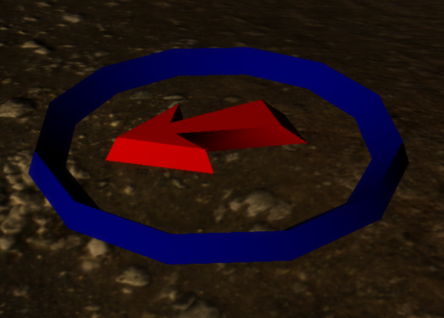
"Passable" or "impassable" depends on a variety of factors such as the slope of the land, obstructions, or water depth. Accessibility Start points are represented by a blue ring with a red arrow. Note that these are different from waypoints, and are only used by the level editor for pathfinding purposes.
Models will often contain collision volumes that will automatically make the places they're located impassible. Likewise, you can set a certain depth of water as being impassible and pathfinding will take this into account.
In order to get pathfinding to work, you must generate your starting point AFTER you create the exportable area, and use the name that is automatically generated for the starting point. DO NOT change the name of the starting point otherwise pathfinding will fail.
Terrain Collision
You will need to block off terrain using the Terrain Block tools ![]() . The first button toggles the display of the terrain blocks, the second button enables you to place terrain blocks, and the third snaps existing blocks to terrain verticies. Left-clicking will start a new block, with additional left-clicks chaining the blocks together. Right-clicking will end the current chain. In addition, right-clicking on an existing block will delete it.
. The first button toggles the display of the terrain blocks, the second button enables you to place terrain blocks, and the third snaps existing blocks to terrain verticies. Left-clicking will start a new block, with additional left-clicks chaining the blocks together. Right-clicking will end the current chain. In addition, right-clicking on an existing block will delete it.
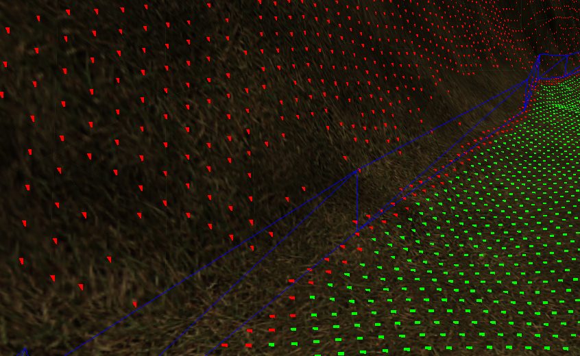
An example of a terrain block chain showing the path finding
Wind
Each level can have one active wind object in it. The location of the wind object doesn't matter. The wind object defines how wind behaves on this level, which is used for such things as flapping banners and swaying trees.
To insert a wind object, right click on the terrain, and choose Insert > New Wind Object.
For other weather effects, see Weather.
Black boxes
When creating an indoor layout you'll need to manually insert "black box" objects on the outer sides of the layout's walls. This allows the player to see through the walls when the camera is outside them, and obscures any parts of models that protrude out where the player shouldn't be able to see them.
Exportable area
A layout requires at least one exportable area. This is the area that the player will be able to operate in and percieve when the layout is exported for use in the game.
It's possible to have a large level with several different exportable areas. The player will have to go through an area transition to travel between exportable areas, just as if they were separate layouts entirely, but by combining them into one level in the level editor it becomes easier to maintain consistency between them. This is particularly useful in layouts where a player in one exportable area can see into the other exportable area but not reach it directly.
The name of an exportable area layout is limited to seven characters. BioWare uses the following naming system:
- Three-letter prefix that describes the region or plot the layout is for. For example, "ost" for Ostagar and environs.
- Three-digit number that uniquely identifies the layout within that region. Increments of one hundred are commonly used for major areas to allow sub-regions to be grouped together.
- A single character identifying variants of the layout. For example, a "d" suffix for the "daytime" version of an exterior layout. "d" is also often used to mean "default", for areas where day and night are irrelevant (deep in a cave, for example).
So for example the layout "ost101d" is a layout in the Ostagar region with a daytime ambience.
Once you have done this you can convert your level into an area by clicking on Do All Local Posts.
Creating an Exportable Area (Room)
The area is created by default whenever a new level file is created. Its default layout name is “<name of exported…” which must be changed to something with seven characters or less. This is the prefix for all resources created specific to this layout. There is no provision for creating multiple areas inside a room based level file.
Creating an Exportable Area (Terrain)
It is possible to have multiple exportable areas in each outdoor level file. These can be created and their properties edited much like any other object in the editor. If you have an exportable area already, you can select it via the drop down menu shown below.
If you want to create or remove an exportable area, use the plus/minus buttons. New areas automatically get an invalid layout name called “<name of exported…” This needs to be changed to something with seven characters or less. This is the prefix for all resources created specific to this layout.
The GREEN box is the area the characters will be able to walk in, so make sure you drag it to cover the entire space you want to be walkable. If you place the green square in one of the corners and then drag diagonally you should be able to expand the box.
* The yellow box is the high level of detail, non-playable border (referred to as the Border).
* The red box is is the low level of detail, non-playable border (referred to as the Vista Border).
These are used for giving depth/backgrounds to your areas. For example the mountains that surround Ostagar or the castle at Redcliffe.
After a new layout entry has been created, you can edit it by clicking on the properties button with the desired area selected in the dropdown.
Exportable area properties
| ⊟ | General | |
| Area ID | This is the ID of the area, this never needs to be changed. | |
| Cutoff Height | ||
| Cutoff System Enabled | ||
| Layout Name | This is the name which will be given to the layout on export, this name should never be longer than 7 characters, and if it is it will be truncated so that it is. This is due to the long names our lightmap files receive, and out 32 character limit. | |
| Name | This is the name that shows up in the drop-down list. | |
| Start Point Name | Artist can specify the name of a startpoint that he/she wants the character to start at when previewing this level in the game. They show up in the hierarchy tree, and can be created using the Start Point Tool. | |
| ⊟ | Atmosphere | |
| Atmo-Sun Color | RGB color values for the sun. Usually white. | |
| Atmo-Sun Intensity | Sun power. Multiplies the extintion and In-scattering terms. | |
| Atmosphere Alpha | ||
| Distance Multiplier | Modulates the distance at which the fog effect is applied. | |
| Earth Reflectance | Specifies the amount of natural color to allow objects to emit. | |
| Mie Multiplier | Modulates the Mie scattering term. | |
| Moon Alpha | ||
| Moon Rotation | ||
| Moon Scale | ||
| Rayleigh Multiplier | Modulates the rayleigh term. | |
| Skydome Model | This is the model to use for the skydome. The resource list that appears when you click here is filtered for models beginning is “sb_”. | |
| Turbidity | Turbidity factor for the Mie term. | |
| ⊟ | Atmosphere Cloud | |
| Color | The cloud layer uses this color. | |
| Density | Lower values make an overcast sky. Higher values give a scattered cloud layer. | |
| Depth | The depth value simulates thickness in the clouds. The lower the value, the darker and more opaque the base is. Higher values simulate more light passing through the cloud layer. | |
| Range1 | First UV offset into the noise texture. | |
| Range2 | Second UV offset range into the noise texture. | |
| Sharpness | : This is a floating point number between 0 and 1, with 0 being no fog and one being a full white out so to speak. | |
| ⊟ | Atmosphere Fog | |
| Fog Cap | ||
| Fog Intensity | The intensity at the far plane. | |
| Fog Max Color | The color at maximum distance. | |
| Tactical Fog Multiplier | ||
| Use Separate Water Fog | ||
| Vertical Fog Zenith | ||
| Water Fog Cap | ||
| Water Fog Intensity | ||
| ⊟ | Buffer Effect 1, 2 and 3 | |
| The properties available will depend on the specific buffer effect selected. | ||
| ⊟ | Layout Sunlight | |
| Char. Sunlight Can Be Occluded | ||
| Character Color | ||
| Character Color Multiplier | ||
| Color | This is the color of the sunlight for the layout. | |
| Color Multiplier | This is the strength of the sunlight. | |
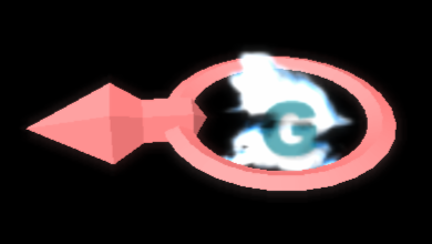
| Direction | This is the direction of the sunlight. It can be typed in manually (a Vector in 3d space), or it can be specified by clicking on the “Set Sunlight” button on the right. Pressing this pops up an icon that shows both the direction of the sunlight and its color. Use the mouse to change it. | |
| Enabled | When this is set to true sunlight is enabled, false it is not. | |
| Soft Shadow Light Angle | ||
| Soft Shadow Num Samples | ||
| ⊟ | Mini Map | |
| Mini Map Position X | ||
| Mini Map Position Y | ||
| Mini Map Size X | ||
| Mini Map Size Y | ||
| ⊟ | Model Low-LOD Lightmap | |
| Downsample Factor | ||
| Max Size | After downsampling is applied, the texture size is checked against the maximum clamp size. | |
| ⊟ | Pathfinding | |
| Character Height | This specifies the average height of a humanoid for the pathfinding info generation. It is specifically used to generate the bounding volume for a creature for the pathing tests. | |
| Clearance | This is currently not being used. | |
| Grid Separation | This is the separation between pathing test points, in the x and y direction. In the default case there would be a pathing point every 0.5 meters. | |
| ⊟ | Terrain Setup | |
| Border Cell Width | This is the number of chunks that will appear in the boundary around the playable area. In order to specify the playable area, use the “define Area” button. | |
| Cell Position X | This is the coordinate of the lower left corner of the exportable area, the numbers are in relation to the chunks and not area or world coordinates. | |
| Cell Position Y | This is the coordinate of the lower left corner of the exportable area, the numbers are in relation to the chunks and not area or world coordinates. | |
| Cell Position Z | This is the coordinate of the lower left corner of the exportable area, the numbers are in relation to the chunks and not area or world coordinates. | |
| Cell Size X | This is the width of the exportable area, in chunks. | |
| Cell Size Y | This is the length of the exportable area, in chunks | |
| Cell Size Z | This is the height of the exportable area. Currently there is only 1 height possible, 1. This will not change for DA. | |
| Lightmap Texture Size | This is the size of the lightmap texture for the terrain chunks. In this case 64 means the texture will be 64x64, which for a chunk size of 64m x 64m will be one texel of lightmap per meter (which is pretty low). | |
| Lightmap Texture Size (Vista) | This is the size of the lightmap texture for a vista chunk, outside the playable area and the border. Again 16 means the texture will be 16x16. | |
| Subdivide Chunks By | ||
| Vista Cell Width | This is the number of chunks that will appear outside the border cells. Anything inside the vista area will not be exported at high LOD. |
Hotkeys
| Key | Function |
|---|---|
| R | Standard Selection |
| Q | 3D Axis Manipulator |
| E | Rotation Manipulator |
| T | Local Coordinates (Toggle) |
| Key | Camera Functions |
| W | Camera Forward / In |
| S | Camera Back / Out |
| A | Camera Pan Left |
| D | Camera Pan Right |
| Key | Brush Size |
| - | Decrease Brush Radius |
| = | Increase Brush Radius |
| Key | Editing |
| Ctrl-X | Cut Selected Object(s) |
| Ctrl-C | Copy Selected Object(s) |
| Ctrl-V | Paste Selected Object(s) |
| Ctrl-Z | Undo last action |
| Ctrl-Y | Redo last action |
| Ctrl-A | Select All |
| Key | General |
| Ctrl-S | Save Map |
| Ctrl-O | Open Map |
| F5 | Refresh Screen |
| Del | Delete Selected Object |
| 5 (Numpad) | Camera Reset/Home (Looks at bottom right corner of map) |
| Ctrl-H | Hide Selected Object(s) |
| Ctrl-/ (Numpad) | UnHides Selected Object(s) |
| Ctrl-* | UnHides all hidden objects |
| Ctrl-\ | Invert Selection |
Tips
Groups are your friend.
Selecting a group will select all models inside that group folder. This allows you to move several objects at the same time as well as apply other settings to that entire group.
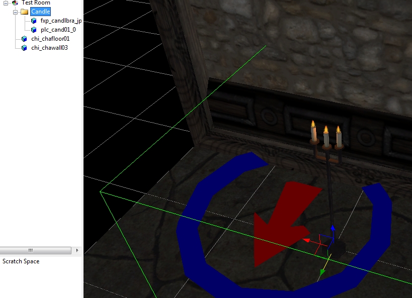
This also makes placing several grouped objects like torches with flame and lights very quick and easy. For example, Setting several candles with flame effects would take a lot of time to place each candle stick individually, and then placing the flame effect exactly on top of the candle for each. By using group folders you only need to set this up once. To place more candles simply select the group folder, Ctrl+C to copy, select its parent group, or other place you want to put the next candle and Ctrl+V to past the new group. Then simply drag it to where you want it.
In addition, the Selection Lock and Visible properties of objects can be useful when trying to manipulate objects when larger objects obscure or get in the way of the desired selection. This is especially handy with water meshes.
